 Southwest
Environmental LimitedSouthwest
Environmental Limited
Southwest
Environmental LimitedSouthwest
Environmental Limited| London |
| 02076 920 670 |
| Exeter |
| 01392 927 961 |
| Manchester |
| 01612 970 026 |
| Bristol |
| 01173 270 092 |
A correctly designed incinerator should ensure adequate destruction of waste, coupled with minimised harmful emissions. Most incinerators built and operated in the UK will need some form of incinerator abatement (system that cleans exhaust gases).
People have mixed feelings about incinerators, but the fact is that we are drowning in plastic waste, and incineration is one of the only options avaiable to deal with pervasive plastic problems such ocean plastic.
In order to ensure these two key aims are met the following variable should be considered:
The operating temperature is probably the most important factor. In order to initiate the destruction waste the threshold temperature must be reached, this varies dependent on the type of waste to be incinerated.
The material must remain long enough in the combustion chamber to reach desired Destruction and Removal Efficiency (DRE). There is a balance to be made here between throughput volume, and achieving DRE.
Pumps, Blowers and Baffles can create turbulence in the combustion chamber. This accelerates the combustion process, and can result in DRE being achieved in a shorter time scale.
Dependent on the pressures reached during operation, varying type of seal will be required to prevent leaks.
Sufficient air must be supplied so as to create complete combustions. Air / Oxygen should be supplied in excess of stoichiometric values, typically ranging fro 110% to 200%.
It is important to select materials that will resist the chemical and thermal environment of the incinerator. This can be a tricky process, as high temperatures, often coupled with presence of hazardous substances can make many materials unsuitable.
Auxiliary system can include feed systems, afterburners, ash removal.
There are 4 main types of incinerator: Liquid Injection, Rotary Kiln, Fixed Hearth and Fluidized Bed.
 In
a typical incinerator supplementary heat and or fuel is added, to the
waste being burnt. This is required to meet the high temperature
requirements, particularly in waste with low calorific content or high
moisture contents.
In
a typical incinerator supplementary heat and or fuel is added, to the
waste being burnt. This is required to meet the high temperature
requirements, particularly in waste with low calorific content or high
moisture contents.
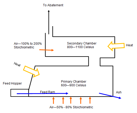
In puts are waste, air and fuel. Outputs are exhaust gases and ash.
Air flow is control to give the ideal balance, for proposed wastes. Waste is burned in the primary chamber at 50% to 80% of the stoichiometric air requirements. This starved air condition causes volatile wastes to be vaporised by the endothermic heat provided in the oxidation of the fixed carbon fraction. Lack of turbulence and low combustion reaction rate, results in minimised particulate entrainment and carryover.
The smoke and pyrolytic products consist mainly of hydrocarbons such as methane and ethane. Which are passed in to secondary chamber, where extra air is added causing spontaneous combustion, or in some case combustion is encourage with addition of extra fuel.
Fixed hearth incinerators typically have a lower capital cots than other types of incinerators, and particulate emissions are quite low owing to lack of turbulence in primary chamber.
The emissions will be required to be abated which we will discuss on the incinerator abatement page.
Rules for Small Incinerators in UK
Incineration of Waste in the UK
The development of Energy from Waste (EfW) facilities, particularly Combined Heat and Power (CHP) plants, is a complex engineering and regulatory undertaking. Successful implementation requires a multi-disciplinary approach that balances combustion efficiency with stringent air quality standards and carbon reduction targets.
Depending on the capacity and waste type, facilities are regulated under different regimes. Navigating these requirements early in the design phase is critical for project viability.
A core challenge in incinerator design is the effective management of flue gases. This involves the integration of sophisticated air abatement systems to remove particulates, acid gases, and heavy metals. When preparing an Air Quality Assessment, it is essential to model the dispersion of these emissions to ensure local air quality neutrality is maintained.
The inclusion of an EfW facility within a development often necessitates a comprehensive Environmental Impact Assessment (EIA). The project must demonstrate how it fits within the local waste hierarchy and contributes to zero carbon objectives. Demonstrating CHP readiness and efficient heat utilization is often a key requirement of the planning statement. SWEL provides the technical authority and accredited expertise (FGS/MIAQM) to manage the entire process, from initial feasibility and environmental permitting to final operational compliance. With over 900 projects delivered across the UK, we ensure your facility meets the highest technical and environmental standards.
Whether you are considering a small-scale clinical waste plant or a large-scale municipal EfW facility, our consultancy offers the specialized insight required for successful delivery.